
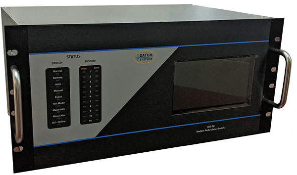
MS-10 REDUNDANCY SWITCH
The MS-10 Redundancy Switch supports up to 10 Prime modems and 1 Standby or Back-up modem. The MS-10 Redundancy Switch provides for both Serial and Ethernet Data Interfaces simultaneously and IF or L-Band switching . The Serial and Ethernet Data interfaces are physically switched from the Prime modems to the Standby modem for Reliable Back-up Operation.
1:N REDUNDANCY SWITCH

Operation
The standard MS-10 Redundancy Switch supports one (1) IF 70/140Mhz transponder (Uplink / Downlink) or one (1) L band Uplink / Downlink, depending on the version of the switch (L-band or IF 70/140MHz). A Multi-Transponder option is available when operation over multiple transponders of 70/140MHz or multiple L-band interfaces (multiple antenna / polarization) is desired. This is a very useful feature when different modems within a redundancy switch system are connected to Uplink / Downlinks of different satellite bands (i.e. C/Ku) or to different satellites.
The MS-10 uses Command Based IF or L-Band Switching on the Transmit side and is used to turn-off the IF output of any failed or offline modem, while the Standby modem is unmuted when taking over for a Prime modem failure. The standard configuration provides for Passive Combiner/Dividers to connect the IF TX and RX interfaces of the modems. The MS-10 Redundancy Switch is supplied as a L band or an IF 70/140MHz system. The customer specifies the IF band for the Combiner-Dividers, either as L- band (950-2050 MHz) or as IF (50 to 180 MHz). An loss less Active Combiner is Optional.
Functionality
The MS-10 Redundancy Switch automatically learns the parameters of all Prime modems. If any Prime modem fails, or requires a manual switchover, the stored parameters of the targeted Prime modem are sent to the Stand-by modem from the MS-10 for immediate switchover and allowing for extremely fast switchover times. The data I/O from the prime modem is also switched to the standby modem at this time. The MS-10 controlls the carriers of both Prime and Back-up Modems. Passive combiners in the Uplink and Downlink provide the connections to the Up / Down converters. Monitor and Control for the MS-10 Redundancy Switch is available on Serial and Ethernet Control Ports.
Construction
The redundancy switches are modular in construction. The Data interfaces plug into the backplane, allowing each modem Interface to be plugged-in or removed without affecting the other modem traffic – within the same or separate bands.
The MS-10 Redundancy Switch has an easily configurable menu which allows the operator to configure the system quickly using a touch screen display & keyboard on the front panel. LED indicators display the fault status of modems and the Standby modem’s Online / Off line status. The Prime modem number which is currently backed up by the standby modem is also displayed.
MS-10 Downloads
Our Products
Download Manuals, Datasheets, Application Guides, White Papers, and other useful tools.